• Система автоматизации с открытым исходным кодом на базе esp8266/esp32 микроконтроллеров и приложения IoT Manager. Наша группа в Telegram

Получение данных с датчика температуры PT100 через ESP32 и MAX31865

Здравствуйте! Нужна помощь в получении данных с термодатчика pt100 через ESP32 и MAX31865.
Я использую micropython. У меня совсем нет опыта в использовании ESP32 и за основу я взяла инструкцию из статьи https://medium.com/@epabrego/1-micropython-esp32-max31865-rtd-pt100-9e9c02e2b55d
Подключение по трехпроводной схеме, как и в статье.
Когда я запускаю main.py, то в результате получаю типа таких данных:
36.244,-784.8231
36.325,-784.8231
36.406,-784.8231
36.486,988.7924
36.567,988.7924
36.648,988.7924
36.728,988.7924
36.809,988.7924
36.89,988.7924
Пока не остановлю.
Я сначала думала, что у меня проблемы с платой MAX31865, потому что перемычку плохо разрезала и могла задеть соседние дорожки, но со следующей платой, на которой я постаралась все аккуратно сделать, я получила такие же данные.
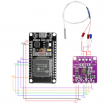
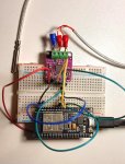
Вот таким образом я подключила:
photo_2024-02-23_18-42-08.jpg
Схема:
u7_sm.png
 

Вложения

fps

Active member
Как оно у вас вообще может запускаться?
Файл adafruit_max31865.txt падает.

Вот это некорректный код для питона:
Код:
import time from micropython
import const
Посмотрите, в примере по вашей ссылке код не такой.

(дальше не смотрел)
 
Как оно у вас вообще может запускаться?
Файл adafruit_max31865.txt падает.

Вот это некорректный код для питона:
Код:
import time from micropython
import const
Посмотрите, в примере по вашей ссылке код не такой.

(дальше не смотрел)
Случайно так сохранилось, зря сохранила как txt. Кодом лучше вставлять...
У меня там:
Python:
import time
from micropython import const

adafruit_max31865.py
Python:
#
# Copyright (c) 2017 Tony DiCola for Adafruit Industries
#
# Permission is hereby granted, free of charge, to any person obtaining a copy
# of this software and associated documentation files (the "Software"), to deal
# in the Software without restriction, including without limitation the rights
# to use, copy, modify, merge, publish, distribute, sublicense, and/or sell
# copies of the Software, and to permit persons to whom the Software is
# furnished to do so, subject to the following conditions:
#
# The above copyright notice and this permission notice shall be included in
# all copies or substantial portions of the Software.
#
# THE SOFTWARE IS PROVIDED "AS IS", WITHOUT WARRANTY OF ANY KIND, EXPRESS OR
# IMPLIED, INCLUDING BUT NOT LIMITED TO THE WARRANTIES OF MERCHANTABILITY,
# FITNESS FOR A PARTICULAR PURPOSE AND NONINFRINGEMENT. IN NO EVENT SHALL THE
# AUTHORS OR COPYRIGHT HOLDERS BE LIABLE FOR ANY CLAIM, DAMAGES OR OTHER
# LIABILITY, WHETHER IN AN ACTION OF CONTRACT, TORT OR OTHERWISE, ARISING FROM,
# OUT OF OR IN CONNECTION WITH THE SOFTWARE OR THE USE OR OTHER DEALINGS IN
# THE SOFTWARE.
"""
`adafruit_max31865`
====================================================MicroPython module for the MAX31865 platinum RTD temperature sensor.  See
examples/simpletest.py for an example of the usage.* Author(s): Tony DiCola, original CircuitPython version
             Chris Osterwood, port _read and _write methods to MicroPython
"""
import math
import time
from micropython import const
import spi_device
#pylint: disable=bad-whitespace
# Register and other constant values:
_MAX31865_CONFIG_REG          = const(0x00)
_MAX31865_CONFIG_BIAS         = const(0x80)
_MAX31865_CONFIG_MODEAUTO     = const(0x40)
_MAX31865_CONFIG_MODEOFF      = const(0x00)
_MAX31865_CONFIG_1SHOT        = const(0x20)
_MAX31865_CONFIG_3WIRE        = const(0x10)
_MAX31865_CONFIG_24WIRE       = const(0x00)
_MAX31865_CONFIG_FAULTSTAT    = const(0x02)
_MAX31865_CONFIG_FILT50HZ     = const(0x01)
_MAX31865_CONFIG_FILT60HZ     = const(0x00)
_MAX31865_RTDMSB_REG          = const(0x01)
_MAX31865_RTDLSB_REG          = const(0x02)
_MAX31865_HFAULTMSB_REG       = const(0x03)
_MAX31865_HFAULTLSB_REG       = const(0x04)
_MAX31865_LFAULTMSB_REG       = const(0x05)
_MAX31865_LFAULTLSB_REG       = const(0x06)
_MAX31865_FAULTSTAT_REG       = const(0x07)
_MAX31865_FAULT_HIGHTHRESH    = const(0x80)
_MAX31865_FAULT_LOWTHRESH     = const(0x40)
_MAX31865_FAULT_REFINLOW      = const(0x20)
_MAX31865_FAULT_REFINHIGH     = const(0x10)
_MAX31865_FAULT_RTDINLOW      = const(0x08)
_MAX31865_FAULT_OVUV          = const(0x04)
_RTD_A = 3.9083e-3
_RTD_B = -5.775e-7
#pylint: enable=bad-whitespace
class MAX31865:
    """Driver for the MAX31865 thermocouple amplifier."""
    def __init__(self, spi, cs, *, rtd_nominal=100, ref_resistor=430.0, wires=3):
        self.rtd_nominal = rtd_nominal
        self.ref_resistor = ref_resistor
        self._device = spi_device.SPIDevice(spi, cs)# Set wire config register based on the number of wires specified.
        if wires not in (2, 3, 4):
            raise ValueError('Wires must be a value of 2, 3, or 4!')
        config = self._read_u8(_MAX31865_CONFIG_REG)
        if wires == 3:
            config |= _MAX31865_CONFIG_3WIRE
        else:
            # 2 or 4 wire
            config &= ~_MAX31865_CONFIG_3WIRE
        self._write_u8(_MAX31865_CONFIG_REG, config)
        # Default to no bias and no auto conversion.
        self.set_bias(False)
        self.set_auto_convert(False)
    def _read_u8(self, address):
        # Read an 8-bit unsigned value from the specified 8-bit address.
        buf = []
        with self._device as device:
            device.write(bytes([address & 0x7F]))
            buf = device.read(1)
        return buf[0]
    def _read_u16(self, address):
        # Read a 16-bit BE unsigned value from the specified 8-bit address.
        buf = []
        with self._device as device:
            device.write(bytes([address & 0x7F]))
            buf = device.read(2)
        return (buf[0] << 8) | buf[1]
    def _write_u8(self, address, val):
        # Write an 8-bit unsigned value to the specified 8-bit address.
        with self._device as device:
            buf = bytearray(2)
            buf[0] = (address | 0x80) & 0xFF
            buf[1] = val & 0xFF
            device.write(buf)
    @property
    def bias(self):
        """Get and set the boolean state of the sensor's bias (True/False)."""
        return bool(self._read_u8(_MAX31865_CONFIG_REG) & _MAX31865_CONFIG_BIAS)
    def set_bias(self, val):
        config = self._read_u8(_MAX31865_CONFIG_REG)
        if val:
            config |= _MAX31865_CONFIG_BIAS  # Enable bias.
        else:
            config &= ~_MAX31865_CONFIG_BIAS  # Disable bias.
        self._write_u8(_MAX31865_CONFIG_REG, config)
    @property
    def auto_convert(self):
        """Get and set the boolean state of the sensor's automatic conversion
        mode (True/False).
        """
        return bool(self._read_u8(_MAX31865_CONFIG_REG) & _MAX31865_CONFIG_MODEAUTO)
    def set_auto_convert(self, val):
        config = self._read_u8(_MAX31865_CONFIG_REG)
        if val:
            config |= _MAX31865_CONFIG_MODEAUTO   # Enable auto convert.
        else:
            config &= ~_MAX31865_CONFIG_MODEAUTO  # Disable auto convert.
        self._write_u8(_MAX31865_CONFIG_REG, config)
    @property
    def fault(self):
        """Get the fault state of the sensor.  Use `clear_faults` to clear the
        fault state.  Returns a 6-tuple of boolean values which indicate if any
        faults are present:
            - HIGHTHRESH
            - LOWTHRESH
            - REFINLOW
            - REFINHIGH
            - RTDINLOW
            - OVUV
        """
        faults = self._read_u8(_MAX31865_FAULTSTAT_REG)
        #pylint: disable=bad-whitespace
        highthresh = bool(faults & _MAX31865_FAULT_HIGHTHRESH)
        lowthresh  = bool(faults & _MAX31865_FAULT_LOWTHRESH)
        refinlow   = bool(faults & _MAX31865_FAULT_REFINLOW)
        refinhigh  = bool(faults & _MAX31865_FAULT_REFINHIGH)
        rtdinlow   = bool(faults & _MAX31865_FAULT_RTDINLOW)
        ovuv       = bool(faults & _MAX31865_FAULT_OVUV)
        #pylint: enable=bad-whitespace
        return (highthresh, lowthresh, refinlow, refinhigh, rtdinlow, ovuv)
    def clear_faults(self):
        """Clear any fault state previously detected by the sensor."""
        config = self._read_u8(_MAX31865_CONFIG_REG)
        config &= ~0x2C
        config |= _MAX31865_CONFIG_FAULTSTAT
        self._write_u8(_MAX31865_CONFIG_REG, config)
    def read_rtd(self):
        """Perform a raw reading of the thermocouple and return its 15-bit
        value.  You'll need to manually convert this to temperature using the
        nominal value of the resistance-to-digital conversion and some math.  If you just want
        temperature use the temperature property instead.
        """
        self.clear_faults()
        self.set_bias(True)
        time.sleep(0.01)
        config = self._read_u8(_MAX31865_CONFIG_REG)
        config |= _MAX31865_CONFIG_1SHOT
        self._write_u8(_MAX31865_CONFIG_REG, config)
        time.sleep(0.065)
        rtd = self._read_u16(_MAX31865_RTDMSB_REG)
        # Remove fault bit.
        rtd >>= 1
        return rtd
    @property
    def resistance(self):
        """Read the resistance of the RTD and return its value in Ohms."""
        resistance = self.read_rtd()
        resistance /= 32768
        resistance *= self.ref_resistor
        return resistance
    @property
    def temperature(self):
        """Read the temperature of the sensor and return its value in degrees
        Celsius.
        """
        # This math originates from:
        # http://www.analog.com/media/en/technical-documentation/application-notes/AN709_0.pdf
        # To match the naming from the app note we tell lint to ignore the Z1-4
        # naming.
        # pylint: disable=invalid-name
        raw_reading = self.resistance
        Z1 = -_RTD_A
        Z2 = _RTD_A * _RTD_A - (4 * _RTD_B)
        Z3 = (4 * _RTD_B) / self.rtd_nominal
        Z4 = 2 * _RTD_B
        temp = Z2 + (Z3 * raw_reading)
        temp = (math.sqrt(temp) + Z1) / Z4
        if temp >= 0:
            return temp# Have to normalize to 100 ohms if temperure is less than 0C for the following math to work
        raw_reading /= self.rtd_nominal
        raw_reading *= 100
        rpoly = raw_readingtemp = -242.02
        temp += 2.2228 * rpoly
        rpoly *= raw_reading  # square
        temp += 2.5859e-3 * rpoly
        rpoly *= raw_reading  # ^3
        temp -= 4.8260e-6 * rpoly
        rpoly *= raw_reading  # ^4
        temp -= 2.8183e-8 * rpoly
        rpoly *= raw_reading  # ^5
        temp += 1.5243e-10 * rpoly
        return temp
 
Другие файлы:
main.py
Python:
## MicroPython Imports
import time
import machine
## Local Imports
import adafruit_max31865 as max31865
RTD_NOMINAL   = 100.0 
## Resistance of RTD at 0C
RTD_REFERENCE = 430.0  ## Value of reference resistor on PCB
RTD_WIRES = 3          ## RTD 3 wires## Create Software SPI controller.  MAX31865 requires polarity of 0 and phase of 1.
## Currently, the micropython on the ESP32 does not support hardware SPI
sck  = machine.Pin(18, machine.Pin.OUT)
mosi = machine.Pin(23, machine.Pin.IN)
miso = machine.Pin(19, machine.Pin.OUT)
spi  = machine.SoftSPI(baudrate=50000, sck=sck, mosi=mosi, miso=miso, polarity=0, phase=1)
## Create array SPI Chip Select pins
#cs1  = machine.Pin(33, machine.Pin.OUT, value=1)
#cs2  = machine.Pin(15, machine.Pin.OUT, value=1)
#cs3  = machine.Pin(32, machine.Pin.OUT, value=1)
#cs4  = machine.Pin(14, machine.Pin.OUT, value=1)
#css  = [cs1, cs2, cs3, cs4]
cs1  = machine.Pin(5, machine.Pin.OUT, value=1)
css  = [cs1]
sensors     = []
idx         = 0
## Create array of active RTD sensors and information about them
for cs in css:
    idx += 1
    sensors.append(
        max31865.MAX31865(
            spi, css[idx-1],
            wires        = RTD_WIRES,
            rtd_nominal  = RTD_NOMINAL,
            ref_resistor = RTD_REFERENCE)
    )
def timestamp():
    return float(time.ticks_ms()) / 1000.0
boot_time = timestamp()

while True:
    data = [timestamp() - boot_time] + [sensor.temperature for sensor in sensors]
    print(','.join(map(str,data)))

spi_device.py

Python:
# The MIT License (MIT)
#
# Copyright (c) 2016 Scott Shawcroft for Adafruit Industries
#
# Permission is hereby granted, free of charge, to any person obtaining a copy
# of this software and associated documentation files (the "Software"), to deal
# in the Software without restriction, including without limitation the rights
# to use, copy, modify, merge, publish, distribute, sublicense, and/or sell
# copies of the Software, and to permit persons to whom the Software is
# furnished to do so, subject to the following conditions:
#
# The above copyright notice and this permission notice shall be included in
# all copies or substantial portions of the Software.
#
# THE SOFTWARE IS PROVIDED "AS IS", WITHOUT WARRANTY OF ANY KIND, EXPRESS OR
# IMPLIED, INCLUDING BUT NOT LIMITED TO THE WARRANTIES OF MERCHANTABILITY,
# FITNESS FOR A PARTICULAR PURPOSE AND NONINFRINGEMENT. IN NO EVENT SHALL THE
# AUTHORS OR COPYRIGHT HOLDERS BE LIABLE FOR ANY CLAIM, DAMAGES OR OTHER
# LIABILITY, WHETHER IN AN ACTION OF CONTRACT, TORT OR OTHERWISE, ARISING FROM,
# OUT OF OR IN CONNECTION WITH THE SOFTWARE OR THE USE OR OTHER DEALINGS IN
# THE SOFTWARE.
# pylint: disable=too-few-public-methods
"""
SPI Bus Device
====================================================
"""
class SPIDevice:
    """
    Represents a single SPI device and manages locking the bus and the device
    address.:param ~busio.SPI spi: The SPI bus the device is on
    :param ~digitalio.DigitalInOut chip_select: The chip select pin object that implements the
        DigitalInOut API.
    :param int extra_clocks: The minimum number of clock cycles to cycle the bus after CS is high.
        (Used for SD cards.).. note:: This class is **NOT** built into CircuitPython. See
      :ref:`here for install instructions <bus_device_installation>`.Example:.. code-block:: pythonimport busio
        import digitalio
        from board import *
        from adafruit_bus_device.spi_device import SPIDevicewith busio.SPI(SCK, MOSI, MISO) as spi_bus:
            cs = digitalio.DigitalInOut(D10)
            device = SPIDevice(spi_bus, cs)
            bytes_read = bytearray(4)
            # The object assigned to spi in the with statements below
            # is the original spi_bus object. We are using the busio.SPI
            # operations busio.SPI.readinto() and busio.SPI.write().
            with device as spi:
                spi.readinto(bytes_read)
            # A second transaction
            with device as spi:
                spi.write(bytes_read)
    """
    def __init__(self, spi, chip_select, *, baudrate=100000, polarity=0, phase=0, extra_clocks=0):
        self.spi = spi
        self.baudrate = baudrate
        self.polarity = polarity
        self.phase = phase
        self.extra_clocks = extra_clocks
        self.chip_select = chip_select
    def __enter__(self):
        ## Locking has been disabled (for now) as MicroPython SPI object does not support it
        # while not self.spi.try_lock():
        #     pass
        # self.spi.configure(baudrate=self.baudrate, polarity=self.polarity, phase=self.phase)
        self.chip_select.value(0)
        return self.spi
    def __exit__(self, *exc):
        self.chip_select.value(1)
        if self.extra_clocks > 0:
            buf = bytearray(1)
            buf[0] = 0xff
            clocks = self.extra_clocks // 8
            if self.extra_clocks % 8 != 0:
                clocks += 1
            for _ in range(clocks):
                self.spi.write(buf)
        ## Locking has been disabled (for now) as MicroPython SPI object does not support it
        # self.spi.unlock()
        return False
 
Измерьте сопротивление датчика отключенного от платы и подключенного.

Гляньте последнее сообщение в https://forum.arduino.cc/t/max31865-pt100/612663/28

Проверьте кодом из ардуино https://learn.adafruit.com/adafruit-max31865-rtd-pt100-amplifier/arduino-code
1. Сопротивления получаются одинаковые, если я правильно понимаю, как измерять сопротивление на подключенном датчике)).
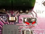
2. Я думаю, что у меня может быть все же проблема с распайкой (у меня пока навык отсутствует). В месте, где надо было разрезать перемычку, сделала разрез. Но сейчас проверяю сопротивление между "2 4" и "3", оно близко к 0. Ведь так быть не должно? И на приближении как будто видно, что там как какие-то перемычки...
243.jpg
(3. До ардуино еще не дошла)
 

CodeNameHawk

Moderator
Команда форума
В месте, где надо было разрезать перемычку,
Может просто припой снять? Кто сказал резать.

Но сейчас проверяю сопротивление между "2 4" и "3", оно близко к 0.
Если измеряете на контактах датчика, то это явно не правильно.
 
Может просто припой снять? Кто сказал резать.


Если измеряете на контактах датчика, то это явно не правильно.
Сняла припой, еще раз разрезала (разрезать, кстати, говорится в сообщении, на которое вы ссылались (первая ссылка)[
Измерьте сопротивление датчика отключенного от платы и подключенного.

Гляньте последнее сообщение в https://forum.arduino.cc/t/max31865-pt100/612663/28

Проверьте кодом из ардуино https://learn.adafruit.com/adafruit-max31865-rtd-pt100-amplifier/arduino-code
Заработало!!! Температуру показывает. Дело было в плохом разделении между контактными площадками 2 и 4. Всем спасибо!!!
 
Сверху Снизу