-
Уважаемые посетители сайта esp8266.ru!
Мы отказались от размещения рекламы на страницах форума для большего комфорта пользователей.
Вы можете оказать посильную поддержку администрации форума. Данные средства пойдут на оплату услуг облачных провайдеров для сайта esp8266.ru -
Система автоматизации с открытым исходным кодом на базе esp8266/esp32 микроконтроллеров и приложения IoT Manager. Наша группа в Telegram
Обсуждение TLSR8269
- Автор темы nikolz
- Дата начала
pvvx
Активный участник сообщества
Это с вами "тр.." уже неделю.Вы задумайтесь, над тем что уже три дня(пардон неделю) вы трахаетесь с устройством ценою 20 долларов. И еще у жены браслет отняли.
Но вы пишите что уже давно имеете TLSR8269 и так и не смогли их запустить, даже EVK выпросили у китайцев
Только вот толку от этого у вас нет. От того и троллите
У меня уже работает TLSR8269 как драйвер USB к любым устройствам на I2C и UART
Китайцы в этом деле сделали всё что вы не смогли это сделать, даже при наличии EVK.
И не забывайте, что на данной неделе я копошусь с несколькими проектами... Из хлама с али с https://esp8266.ru/forum/threads/dt-w5g1.4500/page-2#post-65471 + EportPro EP10 + ...
pvvx
Активный участник сообщества
pvvx
Активный участник сообщества
Да, SWM у TLSR8269 работает.
Для этого надо:
После старта в reg_gpio_pa_gpio (0x586) опустить бит 7 [inline]reg_gpio_pa_gpio &= ~BIT(7); [/inline]
Данные посылаем/читаем в reg_swire_data (0xb0) установив флаги в reg_swire_ctrl1 (0xb1):
FLD_SWIRE_WR = BIT(0) запись байта.
FLD_SWIRE_RD = BIT(1) чтение.
FLD_SWIRE_CMD = BIT(2) стартовый бит.
FLD_SWIRE_CMD - это какой стартовый бит cmd будет у байта при передаче.
После взвода бита FLD_SWIRE_RD он сам очистится когда будут данные в reg_swire_data...
В общем всё просто и подключив хоть из либы bulk USB гоняете swire...
pvvx
Активный участник сообщества
Ещё для информации:
Смешные потуги симулировать TLSR8266/8269 на ESP32 и т.д.:
LowPowerDimmerKnop
Yeelight Bluetooth поворотный диммер
----
IoT - Reverse engineering simple Bluetooth LE devices
----
Xiaomi-Mijia-Bluetooth-Temperature-and-Humidity-Sensor
FreeRTOS over 8269
openocd_tc32
...
PS: и для желающих побороться с BLE в ESP32
ESP32:Примеры/Bluetooth Low Energy: уведомления — Онлайн справочник
pvvx
Активный участник сообщества
Немного пошаманил с TlrsTool. А то работало всего в два-три раза быстрее EVK.
Теперь она перегоняет по скорости записи и чтения EVK во много раз.
В EVK вообще не дождаться когда он прочитает 512 килобайт Flash.
Меня удивляет терпение @nikolz при считывании E104_BT10_G_512.bin на EVK...


PS: Скоро скину новые исхоники и прочее ПО, на старое место выданное в личке...
Скорость увеличена за счет самописного FlashLoadera загружаемого в RAM модуля.
Теперь она перегоняет по скорости записи и чтения EVK во много раз.
В EVK вообще не дождаться когда он прочитает 512 килобайт Flash.
Меня удивляет терпение @nikolz при считывании E104_BT10_G_512.bin на EVK...


PS: Скоро скину новые исхоники и прочее ПО, на старое место выданное в личке...
Скорость увеличена за счет самописного FlashLoadera загружаемого в RAM модуля.
pvvx
Активный участник сообщества
Только бинарнички TLSRTools.beta3.zip
Сделал прогу для работы с TLSR на ESP8266Только бинарнички TLSRTools.beta3.zip
--------------
Отладил режимы:
<>SWS и чтение данных
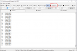
чтение флеш время на 1024 байта:
USB - 140 ms;
EVK - 1240 ms;
ESP8266 - 31 ms.
pvvx
Активный участник сообщества
Для тех кому не понятно, как работает Swire от Telink (и для перевода - ткнуть в эксплорере перевести  )
)
SWM and SWS
SWM (Single Wire Master) and SWS (Single Wire Slave) represent the master and slave device of the single wire communication system developed by Telink. The maximum data rate can be up to 2Mbps.
Communication protocol
The single wire communication protocol developed by Telink is as following:

Figure 1: Sequence diagram for Swire bus communication protocol
One bit contains some units of low level and high level. Sending successively one unit of low level and four units of high level by master represents one bit of 0; while sending successively four units of low level and one unit of high level represents one bit of 1.
Each received byte contains nine bits and some units of low level (end). The foremost bit “cmd” is a flag bit to distinguish between command and data; the “cmd” bit is 0 except for START and END byte.
Regarding to the whole protocol:
SWM and SWS
SWM (Single Wire Master) and SWS (Single Wire Slave) represent the master and slave device of the single wire communication system developed by Telink. The maximum data rate can be up to 2Mbps.
Communication protocol
The single wire communication protocol developed by Telink is as following:
- Pull-up resistor is added to the single wire;
- The voltage of Swire bus is the same as VCC when it is idle;
- Refer to the following sequence diagram:

Figure 1: Sequence diagram for Swire bus communication protocol
One bit contains some units of low level and high level. Sending successively one unit of low level and four units of high level by master represents one bit of 0; while sending successively four units of low level and one unit of high level represents one bit of 1.
Each received byte contains nine bits and some units of low level (end). The foremost bit “cmd” is a flag bit to distinguish between command and data; the “cmd” bit is 0 except for START and END byte.
Regarding to the whole protocol:
- Sending START byte from master to slave starts communication. The bit “cmd” of START byte is 1; data=0x5a.
- Send the 16-bit address containing address high and address low from master to slave.
- Send RW_ID byte from master to slave. Bit7 of RW_ID indicates reading operation (1) or writing operation (0); bit6~bit0 indicate ID of slave.
- For writing operation, master sends data to slave, and the data is written into the memory block of slave. Operation address will add 1 based on current address for each written data; End byte sent from master to slave after all data are written indicates the end of communication. The cmd flag is 1 for END byte; data= 0xff.
- For reading operation, master sends one unit of low level to slave; bus is released. Because of the pull-up resistor, the bus will be pulled to high state. When the period of high level is longer than that of low level, slave starts to send 8-bit data and one unit of low level successively. The bus is released until another unit of low level is sent by master. The reading pointer of slave will add 1 for each read byte. The reading operation comes to an end after the END signal is sent by master.

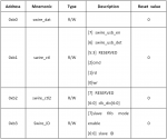
- 0xb0 indicates sending 8-bit data;
- Swire_usb_en indicates whether to use Pin dp of USB as Pin Swire;
- Cmd indicates that cmd bit is sent. 1: the cmd bit is command; 0: the cmd bit is data.
- Rd indicates that reading process starts;
- Wr indicates that writing process starts;
- Clk_div indicates the number of system clock for each bit of Swire;
- Swire_id indicates the ID information in debug process.
pvvx
Активный участник сообщества
Для @nikolz
Скорость прошивки SPI-Flash ограничена самими тайменгами стриания/записи Flash и лежит в пределах до 200 килобайт в сек. Т.е. более этого трафика с внешним чипом для записи Flash не требуется, но можно
- В SDK Telink есть исходники и в либе поддержка USB1.1 bulk. (в usb.o, usb_bulk.o, usb_ctrl.o, usb_desc.o)
- USB_VID и USB_PID задается (см. примеры)
- SWM пин работает на TLSR8269
- По умолчанию, после сброса чипа TLSR8269 при кварце 12 и 16 МГц, битовая скорость ответа чипа по swire от 1.2 до 1.6 Mbps
Скорость прошивки SPI-Flash ограничена самими тайменгами стриания/записи Flash и лежит в пределах до 200 килобайт в сек. Т.е. более этого трафика с внешним чипом для записи Flash не требуется, но можно
pvvx
Активный участник сообщества
В итого: Полностью теоретически и практически подтверждаемая скорость прошивки TLSR8269 по swire составляет 200 килобайт в сек.
Есть некая зависимость от времени стирания. Flash выполняет стирание автоматически и время стирания пустого или записанного сектора/блока/всего чипа разнится сильно. Но данные приведены для самого долгого времени стирания при +25С.
Есть некая зависимость от времени стирания. Flash выполняет стирание автоматически и время стирания пустого или записанного сектора/блока/всего чипа разнится сильно. Но данные приведены для самого долгого времени стирания при +25С.
А должно быть 5 мс, если сделать нормально.чтение флеш время на 1024 байта:
ESP8266 - 31 ms.
pvvx
Активный участник сообщества
Начните с первого несоответствия:pvvx,
правильно я Вас понял, что Вы получили время чтения из флеш 1024 байт 5 мс.
USB показывает для TLSR8266 130 мс.
Т е у Вас в 26 раз быстрее. Все верно? Ничего лишнего Вы не преувеличили?
Вы случайно с чтением SRAM (USB показывает 10 мс) не перепутали?
- Сектор Flash с ID: 544013 имеет размер 4096 байт.
- Передача по swire 1024 байт при скорости 2 mbps составляет (10 * (1024 + 5))/2000000 = 0.005145 сек. Это и есть ваши 5 mc. Но никто не запрещает увеличить скорость swire более 2 mbps путем установки делителя до '2'. По умолчанию там '5'.
pvvx
Активный участник сообщества
@nikolz - Для наглядности привожу вам вырезанные куски из исходников моего FLoader:
Вот через [inline]struct sext[/inline] CPU и 'общается' по внешнему управлению по swire.

В программе выводится:
Buffer: 808А90:2000
Что означает, что адрес гарантированного* буфера = 0x808А90 и его размер 0x2000.
*гарантированного - можно задать любой (см. код.)
PS: Полные исходники для сборки проекта FLoader выдаются в личке 'постучавшимся'.
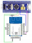
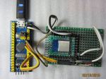
В программу SM32 добавлен опрос всех GPIO STM32F103 и их управление. Но пока в основной программе реализовано только чтение. Нужно было для отладки модуля путем соединения их с ногами модуля... Например вместо 'светодиодов'.
Код:
typedef struct {
    volatile u32 faddr;
    volatile u32 pbuf;
    volatile u16 count;
    volatile u16 cmd;
    volatile u16 iack;
    volatile u16 oack;
} sext;
sext ext;
u8    buff[8192];
//.... Основная  Процедура
    ext.faddr = 0;
    ext.pbuf = (u32) buff;
    ext.count = sizeof(buff);
    ext.cmd = FLASH_GET_JEDEC_ID;
    ext.iack = 1;
    ext.oack = 0;
    u16 ack = 0xffff;
    while(1) {
        while(ack == ext.iack);
        ack = ext.iack;
        switch(ext.cmd) {
            case FLASH_READ_CMD:
                flash_read_page(ext.faddr, ext.count, (u8 *)ext.pbuf);
                break;
            case FLASH_WRITE_CMD:
                flash_write_sector(ext.faddr, ext.count, (u8 *)ext.pbuf);
                break;
            case FLASH_SECT_ERASE_CMD:
                flash_erase_sector(ext.faddr);
                break;
            case FLASH_GET_JEDEC_ID:
                ext.faddr = flash_get_jedec_id();
                break;
            case 0xF3:
                analog_write_blk((u8)ext.faddr, (u8 *)ext.pbuf, ext.count);
                break;
            case 0xF4:
                analog_read_blk((u8)ext.faddr, (u8 *)ext.pbuf, ext.count);
                break;
        }
        ext.oack++;
    }

    REG_ADDR8(0x6f) = 0x20;   //mcu reboot
    while (1);
В программе выводится:
Buffer: 808А90:2000
Что означает, что адрес гарантированного* буфера = 0x808А90 и его размер 0x2000.
*гарантированного - можно задать любой (см. код.)
PS: Полные исходники для сборки проекта FLoader выдаются в личке 'постучавшимся'.
В программу SM32 добавлен опрос всех GPIO STM32F103 и их управление. Но пока в основной программе реализовано только чтение. Нужно было для отладки модуля путем соединения их с ногами модуля... Например вместо 'светодиодов'.

